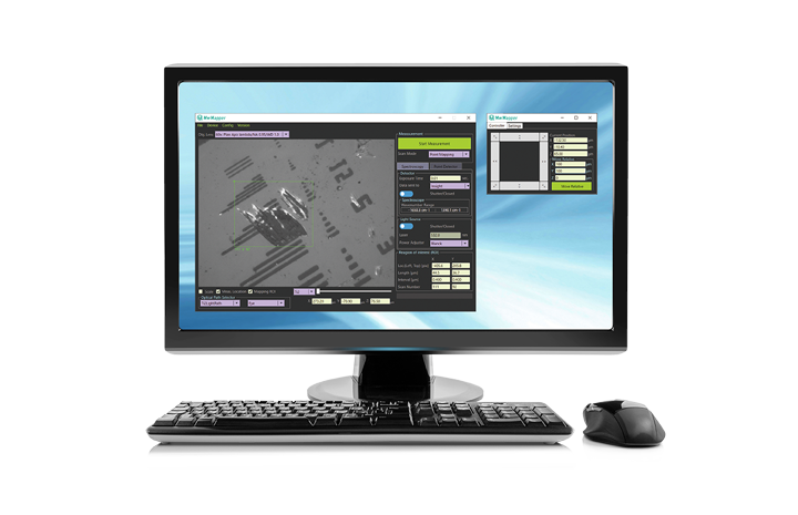
Control & acquisition software for hyperspectral imaging
MwMapper integrates and controls all devices
incorporated in laboratory-built instrument to
achieve full automation of any measurement sequence.
The "Micro World Mapper" serves all microscope users.
HIGHLIGHT
The measurement sequence can be freely
configured, allowing full automation.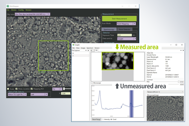
Real-time data display makes it easier
to examine measurement conditions.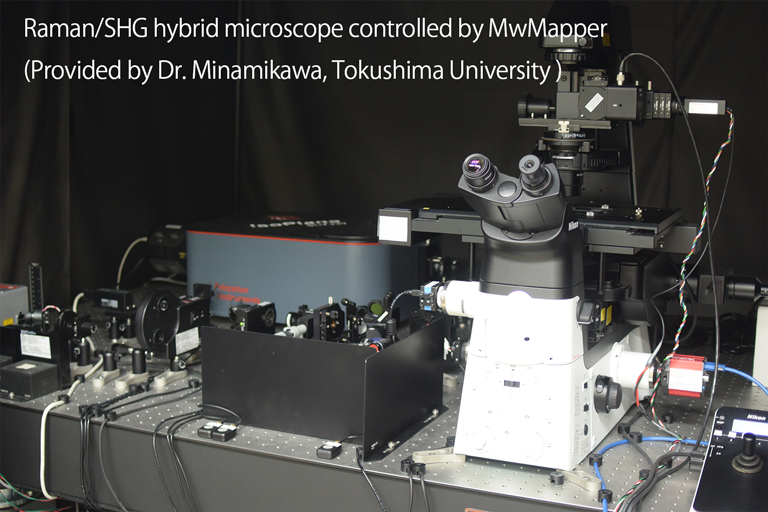
Compatible with Raman, fluorescence,
photoluminescence, LIBS and so on.


- Overview
- Case Examples
- Functions 01
- Functions 02
- Devices
- Specs
- FAQ
- Custom order
- Papers
Overview
MwMapper is an integrated software for home-built or laboratory-built instruments for spectroscopy and microscopy. MwMapper unify the controls of any kinds of basic devices which constitute spectroscopic microscope system and provides integrated and intuitive user-interface.
In research fields or development site, home-built measurement systems often become very complicated where a variety of devices such as microscopes, lasers, motorized stages, detectors and so on, exist together and intercommunicate between them. For its operation, the most difficulty happens when measurement becomes routine or when colleagues who are not developer of the system use because of lack of easy operation software to control the system as one system. MwMapper provides easy, flexible, intuitive and integrated interface for them.
MwMapper is named as Micro World Mapper. Its mission is to collect any information everywhere under a microscope and put it into one map (Data).
The prominent feature is a graphical user interface (GUI) which enables to set region of interest (ROI) on a sample image taken by a microscope camera by click-and-drag.
With this strong interface, users can perform their routine quite efficiently. To achieve it, MwMapper recognizes, controls and unifies any kinds of devices of different manufacturers.
MwMapper, then, can make seamless cooperation of the devices and provide one-stop measurement and functions.
MwMapper is dedicated to control hardware and have no roles to deal with measured data. MwMapper cooperates with another software, Insight which is data-view and analyzing software.
The data measured by MwMapper system are sent to Insight automatically and Insight starts to analyze it. In addition, MwMapper has external trigger out to cooperate with other software and hardware.
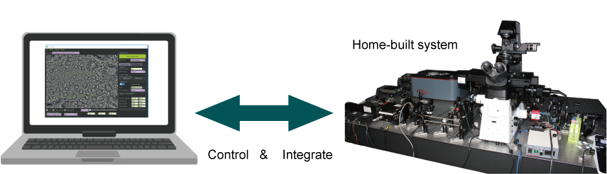
Fig. : Integrated software controlling different kinds of devies
Main functions
- Recognition, control and unity of any kinds of devices
- User interface for setting ROI on a camera monitor with click-and-drag
- Interface for measurement condition of two-dimensional images
- Interface for measurement condition of spectra
- Interface for measurement condition of hyperspectral images
- Interface for setting auto-sequence before/after measurement
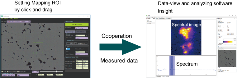
Fig.: MwMapper GUI and cooperative software Insight
Applicable system
- Microscope
- Laser Scanning microscope
- Spectroscope
- one-shot spectrum measurement with CCD/line sensor
- Wavelength scanning measurement
- Grating scan
- Laser wavelength scan
- Hyperspectral mapping/imaging system
- Hybrid system with any combination above
Application
- Laser scanning microscope, Confocal microscope
- SHG microscope (Second Harmonic Generation)
- Fluorescence microscope
- Raman microscope
- Photo-luminescence (PL) spectroscopic microscope
- Reflection spectroscopic microscope
- Scatting spectroscopy microscope
- Absorption spectroscopy and microscope
- Microscopic FTIR spectroscopy
- Photothermal spectroscopy and microscopy
- LIBS (Laser Induced Breakdown Spectroscopy) microscope
- Combination of applications above
Case Examples
Case Examples are introduced here.
Each system has individual combination of baisc devices or uqique devices.
MwMapper changes GUI adapt to the combination of devices and display the most appropriate GUI automatically.
UI for microsocpe are common among these different systems.
Microscope camera is the most common deivces. Other microscope devices such as an illumination device, a XYZ stage, optical path selectors and others, may be manual controlled.
GUI for manual control deivces will not be shown.
MwMapper classify detection system to three types and has three GUIs for each detection system. It is possible to equip plural different detectors.
- Point detector for two-dimensional imaging with scanning. (photo-diode/photomultiplier tube)
- One-shot spectrograph:Spectrograph with an array detector (two-dimensional CCD/line sensor)
- Wavelength scanning spectrograph: Grating scan/Wavelength tunable laser and a point detector (photo-diode/photomultiplier tube)
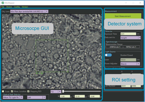
Fig.: Main display
Scanning of a measurement point is important concept in MwMapper. MwMapper defines measurement of an image with a stage scanning as "Mapping" and with laser beam scanning as "Imaging".
- Mapping : Stage scanning (Move a specimen with fixed a measurement point in a microscope view-field.)
- Imaging : Laser seam scanning (Move a measurement point in a microscope view-field while specimen is fixed.)
Case1:Spectroscopic microscope with laser excitation
Laser is guided into a microscope and is focused on microscope specimen. Scattering or emission light at the focus is collected to and is dispersed in spectrograph and detected by the detector.
Raman spectroscopy , photoluminescence spectroscopy and LIBS(Laser Induced Spectroscopy) are applicable.
■Constitution
- Microscope
- One-shot spectrograph
- XYZ Stage
- Laser system
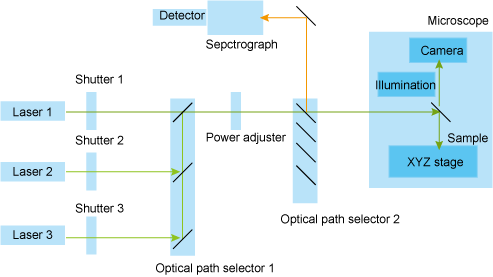
Fig. :Spectroscopic microscope with laser excitation
Case 2 : White-light spectroscopy and microscope
While-light illuminates microscope specimen and reflection/transmission/scattering light from a certain point/area at specimen, where is imaged onto the detector, is collected to and is dispersed in spectrograph and detected by the detector.
The imaged area might be a point or line depending on the detector type. Reflection spectroscopy, absorption spectroscopy and scattering spectroscopy are applicable.
■Constitution
- Microscope and white-light illumination device
- One-shot or Wavelength scanning spectrograph
- XYZ stage
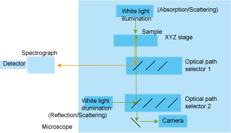
Fig.: White-light spectroscopy and microscope
Case 3:Laser Scanning Microscope
Laser beam, deflecting by galvano mirror scanner, is guided into microscope and is focused onto the sample.
The intensity of reflection, scattering or emission light from the focus is measured while laser beam scanning.
Confocal system has a pinhole to reject light from out-of-focus in front of the detector.
Reflection confocal microscope, fluorescence confocal microscope are applicable. Thermo-reflectance microscope is also achievable.
■Constitution
- Microscope
- Point detector
- Laser beam scanner
- Laser System
- (XYZ stage is used in combination)
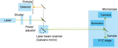
Fig.: Laser Scanning Microscope
Case 4:Laser wavelegnth scanning spectroscopy and microscope
Tunable laser is guided into a microscope and is focused on microscope specimen.
Scattering, emission or transmission light at the focus is detected by a pint detector.
With laser wavelength scanning, the spectrum is obtained.
For photothermal spectroscopy, another laser, wavelength-fixed laser is guided co-axially with the tunable laser as a probe and its reflection of scattering light is detected.
■Constitution
- Microscope
- Wavelength tunable laser
- XYZ stage
- Wavelength-fixed laser as a probe (for photothermal spectroscopy only)
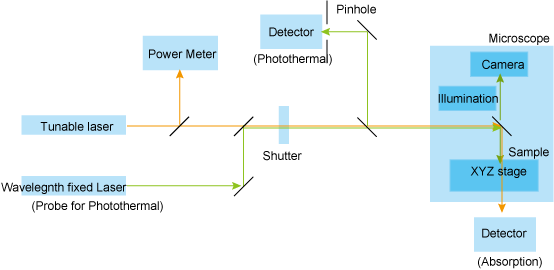
Fig.: Laser wavelegnth scanning spectroscopy and microscope
Case 5:Hybrid system
Hybrid system which combines different detector system of point detector, one-shot spectrograph, and wavelength scanning spectrograph is applicable. As one of example of the combination, the combination system of point detector and one-shot spectrograph are shown in Fig. Intensity measurement with the point detector and spectrum measurement with the spectrograph are done simultaneously. With stage scanning, the intensity distribution image and hyperspectral image are obtained at the same time. Insight can receive both data at the same time and display at once. MwMapper is designed flexibly for the hybrid system such as SHG imaging and Raman hyperspectral imaging, Confocal reflection imaging and Raman hyperspectral imaging, Raman and Photothermal imaging and so on.
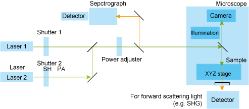
Fig.:Hybrid system (One-shot spectrograph and point detector for laser scanning microscope)
Actual example: Raman and SHG microscope (Hybrid system)
This system equips one-shot spectrograph for Raman spectroscopy and a point detector to detect forward scattering light of SHG. Two lasers, one for Raman excitation and the other for SHG excitation are guided into microscope co-axially and are irradiated at the same point on the sample. Then Raman spectrum and SHG intensity from the same point are measured at the same time. Because laser beam scanner is equipped, this system can do imaging quickly.
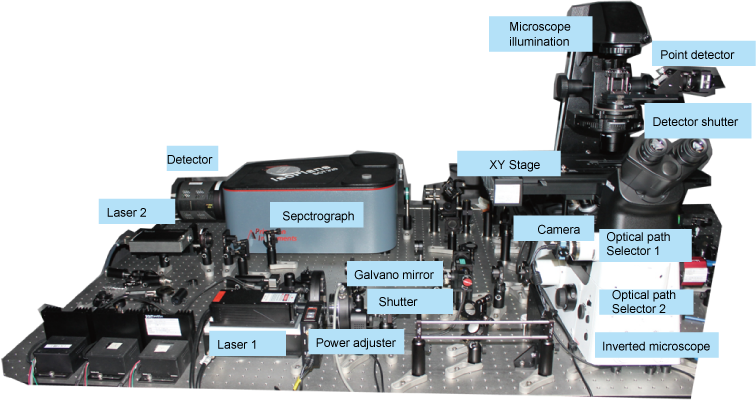
Fig.:Actual example: Raman and SHG microscope (Hybrid system)
Note) This picture is provided By courtesy of Prof. Takeo Minamikawa in Tokusima Univ.
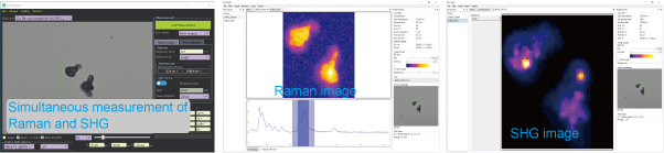
Fig.:Raman image and SHG image of Lithium niobate micro-crystals measured simultaneously.
Note) These data are provided By courtesy of Prof. Takeo Minamikawa in Tokusima Univ.
Key features
How to set measurement area (ROI: Region Of Interest)
Just use mouse click-and-drag on microscope view-field.
ROI can be set intuitively.
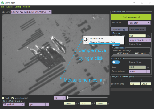
Fig.: Right click moves a sample to the measurement point with a XY motorized stage.
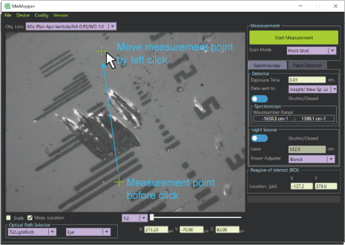
Fig.:Left click moves the measurement point where you click with laser beam scanner.
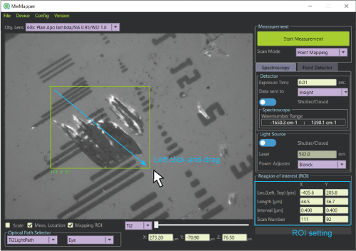
Fig.: Left click-and-drag sets ROI of mapping/imgaing.
Scanning mode of measurement
MwMapper defines coordinate X-axis and Y axis as horizontal and vertical direction in a microscope view field and Z-axis as perpendicular direction to the view-field. Mapping/Imaging can be achieved in XY plane, YZ plane and、XZ plane.
Note: Scanning in Z-axis is only with Z drive, not with laser beam scanning.
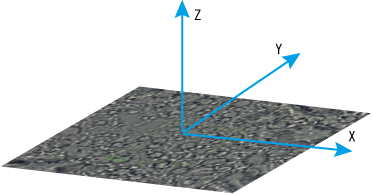
Fig.:Coordinate of MwMapper
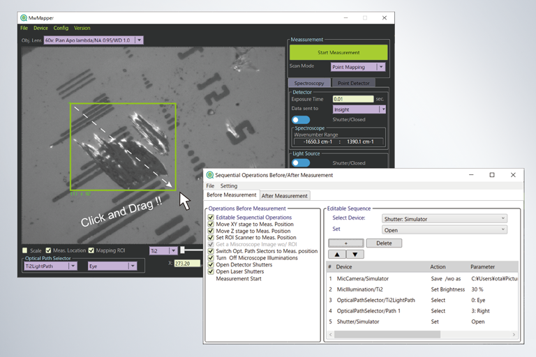
Automatic sequence of measurement
Measurement starts with "Measurement button" After starting, several devices and functions are executed sequentially and automatically.
The sequence includes the preparation before the measurement and the post handling as shown in the figure. The sequence of preparation and the post handling is set by users flexibly.
■Setting item
- Laser Shutter; On/Off
- Detector Shutter; On/Off
- Microscope illumination brightness; 0-100%
- Measurement position with the scanner
- Position of XYZ motorized stage
- Optical path selector including selectable filters
- Each transition time between the items
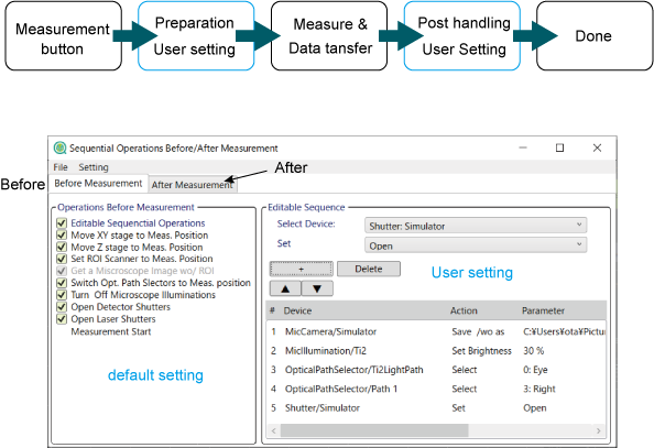
Fig.:Setting window for the sequences of measurement (Sequentail Operations Before/After Measurement)
Detection system
MwMapper of current version (1.4) equips three types of detection system as below. Because measurement parameters differ between detection systems, each system has each GUIs.
■3つの測定システム
- One-shot spectrograph
- Point detector
- Wavelength scanning spectrograph
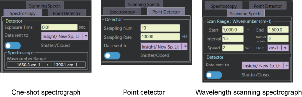
Fig.:GUIs for three detection systems
Data handling while measurement
Spectrum mapping measurement often takes long time as several minutes to more than hours. Because MwMapper communicate with Insight continuously and transfers data, it is possible to update data view, adjust the contrast and control the selection of spectral band to create spectral images.
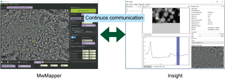
Fig.:Data handling while measurement
Basic devices
XY motorized stage and Z drive
These are devices to move microscope samples and are controlled with four UIs. ■User Interface (UI)
- Click-and-Drag of a middle button (or mouse wheel) on microscope view-field to move in a XY plane.
- Stage control window for XYZ movement.
- Short cut for XYZ movement. (X axis: "X" key + mouse wheel rotation, Y axis: "Y" key + mouse wheel rotation, Z axis: "Z" key + mouse wheel rotation)
- Select from context menu with right-click to move in a XY plane. (1: Move right-click position to the center of the view-field. 2: Move right click position to the measurement position of the view-field.)
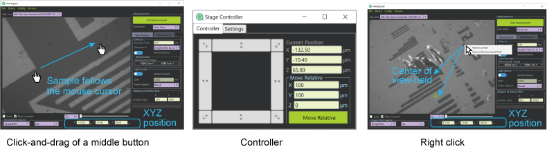
Fig.UIs for XY motorized stage and Z drive
Microscope camera
Camera takes picture of sample surface under microscope. The picture is saved automatically at measurement. Software functions provide Zoom-in and Zoom-out. Zoom-out is useful to set bigger mapping ROI than the view field.
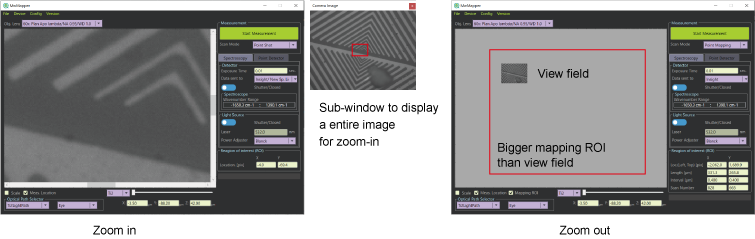
Fig.: Microscope image taken by the camera. Zoom-in image (digital magnification) and Zoom-out image (digital minification).
Microscope illumination
Illumination is for microscope observation. Various kinds of illumination such as bright-field transmission illumination, bright-field reflection illumination, dark-field transmission illumination, dark-field reflection illumination, mercury lamp for fluorescence excitation and so on. The number of illuminations which MwMapper can handle is not limited. The brightness is controlled between 0 % - 100 %.
All illumination will be turned off while measurement and turned on after measurement automatically by default setting.
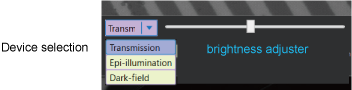
Fig.: GUI for Microscope illumination
Revolver for objective lenses
Revolver is a device to select an objective lens. MwMapper recognizes the selected objective lens and its magnification and transmission data. The magnification reflects the scale information in MwMapper and set the mapping step size correctly. When power meter is equipped in the system, the transmission data can be used for the compensating laser power between at sample and at the power meter. If the revolver is motorized type, the objective lens is automatically changed when the objective lens is selected on MwMapper.
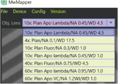
Fig.: GUI for revolver and objective lens selection.
Laser System
Laser System is composed of a laser and its related devices. Laser is utilized for the excitation source of Raman scattering, SHG, fluorescence and so on. Tunable Laser is utilized for the broad band light source of spectroscopy. The related devices are a shutter controlling On/Off of laser irradiation, a power adjuster such as ND filters, a power meter to monitor laser power, polarization device controlling the polarization state, and so on.
■Constitution
- Laser [Power, Wavelength, others]
- Shutter [On/Off]
- Power adjuster [0-100%]
- Power meter [W]
- Polarization device [Polarization angle, polarization degree]
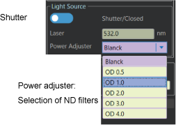
Fig.: One of GUI examples for a Laser system
Optical path selector
Optical path selector is a device which selects the optical path and the filter in optical path as well. Optical path selector has plural choices and "Neutral Path" and "Measurement Path" are defined as the path for not measurement, and the path for measurement, respectively. By default, the optical path selector changes the path from "Neutral Path" to "Measurement Path" just before measurement and from "Measurement Path" to "Neutral Path" after measurement automatically. User can set this automatic sequence at the measurement flexibly.
The number of the optical path selector is not limited in MwMapper.
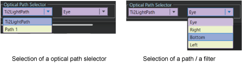
Fig.: GUI of Optical path selector
Trigger input and output
Trigger input and output devices is utilized to cooperate with other software and to make hardware cooperate. MwMapper of current version defines 1 channel trigger input and 1 channel trigger output for measurement start trigger and scanning trigger.
Laser beam scanner (Measurement point scanner) and laser beam shaper
Laser beam scanner or measurement point scanner is a device to move a measurement point in microscope view-field, which is usually equal to the focus position of the laser when laser is irradiated.
Note that the term of "a measurement point" is used because a measurement point is always imaged onto the detector even though without laser irradiation such as with white-light spectroscopy.
The most case of the measurement point scanner is a galvano mirror. In MwWmpper, laser beam scanner is controlled such that the left-click point of the view-field is set as the measurement position. Laser beam shaper is a device to transform the focal point to other shape such as line or multi-foci points of M columns by N rows. MwMapper with current version can uses only line illumination device not for multi-foci device. When line illumination device is set, MwMapper display "Line-shot", Line-Imaging, "Line-Mapping" and others in the "Scanning mode" combo-box control. when Line mode is selected in the Scanning Mode, line illumination device is set in the path automatically and ROI shown in the view-field is changed to for line-mode.
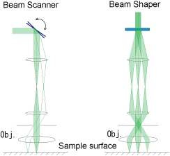
Fig.: Laser beam scanner and laser beam shaper
Devices to be integrated
As internal structure of MwMapper, MwMapper has three layers as "User interface" layer, "Abstract device" layer and "Actual device" layer as shown in fig. to achieve device platform where any kinds of devices work and cooperate together. "Abstract device" layer defines the role and functions of any devices and unify the control method that differs from different products of different manufacturers and, then, provide common command set to the "User interface" layer. Because of this mechanism, it makes it possible to control the system which is the combination of many devices with the integrated interface of MwMapper after user describe the actual devices at the abstract devices in the setting file.
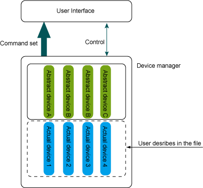
Fig.: Concept of internal structure
Defined abstract devices (Version 1.4.6)
- Microscope
- Camera for microscope
- XY motorized stage for microscope
- Z Drive for microscope
- Revolver as an objective lens selector for microscope
- Illumination device for microscope
- Optical Path Selector
- Spectrograph
- Array detector for spectrograph(1D/2D)
- Point detector for Laser Scanning Microscope
- Shutter for detector
- Wavelength-fixed Laser
- Tunable laser
- Shutter for laser
- Laser Power adjuster
- Laser Power meter
- Laser Beam Shaper
- Laser Beam Scanner (Measurement point scanner)
- Trigger input, Trigger output device
Actual devices (Note that [] shows corresponding abstract devices)
If you have devices which are not listed below, please contact us.
- Ti2E Microscope / Nikon [Microscope, XY motorized stage, Z Drive, Revolver, Illumination device, Optical Path Selector (Light Path), Optical Path Selector (Turret)]
- USB camera / ImagingSource [Camera]
- BIOS series (SHOT-702 Controller)/ SIGMA KOKI [XY motorized stage]
- BIOS series (FC-101 Controller)/ SIGMA KOKI [XY motorized stage]
- Motorized XY Stage (SEMPD01 controller)/SCIENCEEDGE [XY motorized stage]
- Z Drive (SEMPD01 controller)/SCIENCEEDGE [Z Drive]
- SpectraPro/ Princeton Instruments [Spectrograph]
- IsoPlane/ Princeton Instruments [Spectrograph]
- PIXIS/ Princeton Instruments [Array detector (2D) for Spectrograph]
- ProEM/ Princeton Instruments [Array detector (2D) for Spectrograph]
- KURO/ Princeton Instruments [Array detector (2D) for Spectrograph]
- PyLoN/ Princeton Instruments [Array detector (1D/2D) for Spectrograph]
- Newton/ Andor Technology [Array detector (2D) for Spectrograph]
- DAQ device (ADC)/National Instruments [Point detector / Laser Power meter]
- DAQ device (DAC)/National Instruments [Laser Beam Scanner]
- DAQ device (GPIO)/National Instruments [Shutter/Laser Beam Shaper/Trigger input, Trigger output]
- Shutter controller SC10/Thorlabs [Shutter]
- Shutter driver VCM-D1/ Vincent Associates [Shutter]
- Motorized Filter Wheel, FW102C, FW212C/ Thorlabs [Laser Power Adjuster]
- Rotational ND filter/ SCIENCEEDGE [Laser Power adjuster]
- Ventus/ Laser Quantum [Wavelength-fixed laser]
- Gem/ Laser Quantum [Wavelength-fixed laser波長固定レーザー]
- Opus/ Laser Quantum [Wavelength-fixed laser]
- SuperK EXTREAME & VARIA/ NKT Photonics [Tunable laser]
- MIRcat-QT/Day Light Solutions [Tunable laser]
How to set actual devices
Actual devices are described in the setting file of XML format (.xml). MwMapper loads and understand the setting file while starting and, then, starts to control the system after the initialization of all devices. In addition to the information of the actual single devices, the unique information of the system such as cooperation of devices and system adjustment parameters such as microscope scale are described in the setting file. Fig. below shows the example of the setting file (.xml) opened with Microsoft XML Notepad (free software).
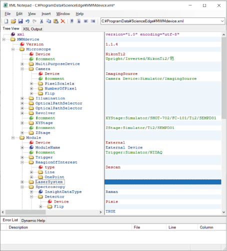
Fig.: Setting file (.xml) for describing actual devices
Specifications
- Operating environment: Windows 10 64bit OS
- Version: V.1.4
- Applicable devices: refer to the item of "Devices to be integrated".
- License: Permanent license with a USB dongle.
- Deliverable: An installation DVD, a USB dongle
- Support: We support to make the setting file for your initial installation by remote/online method. On-site setup service charges additionally.
History
2020/10/01 : Ver 1.4.6 was released.
FAQ
Q1. I would to consider to buy with demonstration. Is demonstration available?
A1. Yes. We offer customers to use MwMapper with full functions for 1 month. We will lend the USB dongle license limited with 1 month.
Note that it charges for making the setting file and installation by us. When ordered, the amount for the installation charge will be discounted.
Q2. I have XY motorized stage of Prior Scientific product. Does it work with MwMapper?
A2. No. with current version. (Ver 1.4.6). However, we can add standard devices easily. Please ask us when you consider to order.
Customization
MwMapper functions
If you find the functions that MwMapper with the latest version does not have but you need, please ask us. We can develop the functions as customization.
Other software development
We are willing to develop your own original software for your measurement system or data analyzing purpose. Do not hesitate to contact us.
Custom made measurement system
We can offer to design and built your own measurement system such as Raman microscope, white-light spectroscopy and microscope, laser sytem and so on. Do not hesitate to contact us.
Papers
Takeo Minamikawa, Mayuko Ichimura-Shimizu, Hiroki Takanari, Yuki Morimoto, Ryosuke Shiomi, Hiroki Tanioka, Eiji Hase, Takeshi Yasui and Koichi Tsuneyama
“Molecular imaging analysis of microvesicular and macrovesicular lipid droplets in non-alcoholic fatty liver disease by Raman microscopy”
Sci. Rep., 10, 18548 (2020)
