Lab tool
Image Rotator Mirror Unit
(K-Mirror)
The triple mirror unit generates an inverse or rotational
image without chromatic aberration and can be used
for a converging, diverging and collimated beam.
IRMU overcomes the weaknesses of dove prism.
- Overview
- Specifications
- Other info
Overview
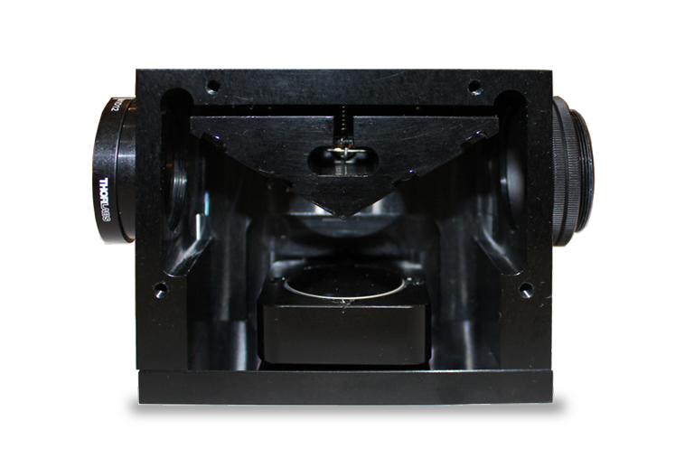
Image Rotator Mirror Unit (IRMU) is a monolithic unit of three mirrors with the mirror adjustment mechanism to generate an inverse or rotational image. When the three mirrors are viewed from the cross-sectional direction, the middle mirror and the front and rear mirrors look like the backbone and legs of a capital "K," hence the product is also called a "K-Mirror".
With the rotation of the unit along the optical axis, the image is rotated with the double angle. Mirror adjustment mechanism makes it possible to adjust the optical axis to the rotational axis of the rotation device. ※) Because of the reflection optics, this unit can be applied in not only collimated beam but also the focusing beam. Furthermore, because the reflection optics is free from the chromatic aberration, the unit can be also used in spectroscopy.
- ※
- The rotation device is provided optionally.

Dove prism is another optical device to generate an inverse or rotational image. While dove prism is cost effective, it has several disadvantages over the Image Rotator Mirror Unit as follows;
Disadvantages of Dove prism
- Focusing beam or divergent beam is not applicable.
- Chromatic aberration due to the dispersion of the refractive index.
- The reflection surfaces are fixed and are not adjustable though it has a finite tolerance※ between the optical axes between the ingoing and the outgoing beam.
(If the angle error is ignored, it is impossible to adjust so that the rotation center of the image is fixed during the rotation. It is quite difficult to adjust axes after fixing the unit to the rotation device.)
- ※
- The angle tolerance of the Dove prism is generally is 10~20µrad.
The Image Rotator Mirror Unit has advantages over the Dove prism with regards to therse points.
Function
- To inverse an image
- To rotate an image with the combination with the rotational device.
Features
- Applicable for a converging and a diverging beam.
- Chromatic aberration Free. Suitable for spectroscopy.
- Fine adjustment of reflection mirrors.
- Monolithic unit.
Applications
- Angle adjustment of the line beam in a Structured Illumination Microscopy (SIM)
- Angle adjustment of the sheet face in a light sheet microscopy.
- Angle adjustment of the illumination of a spectroscopic Photoactivated Localization Microscopy (PALM).
- Simplification of an echelle spectrograph. (The optics can be aligned in one plain.)
- Others
Specifications and Configuration
Configuration
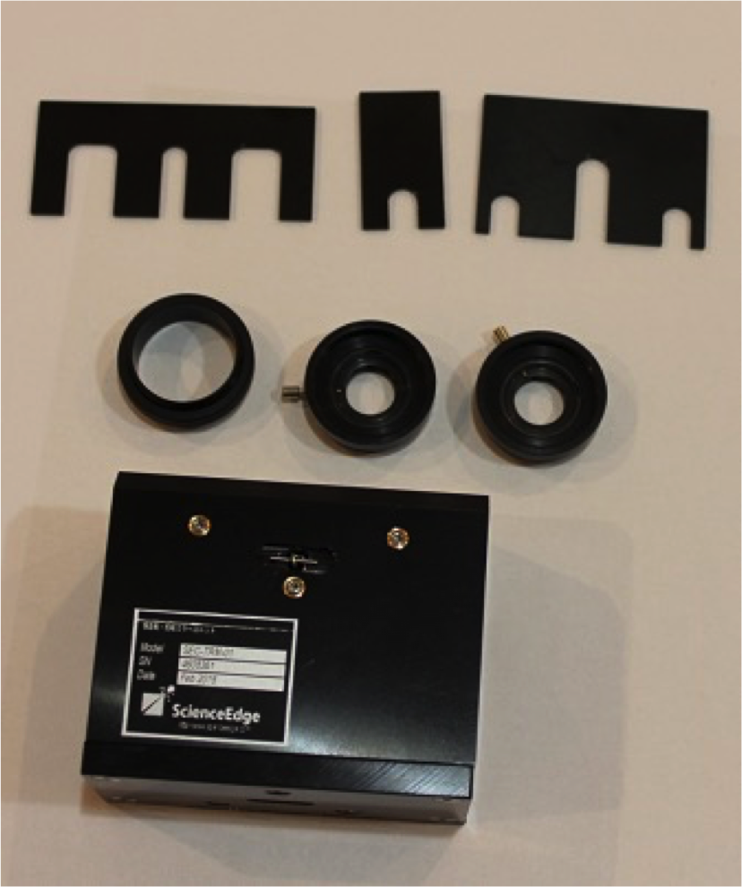
- An Image Rotator Mirror Unit
- Two Iris Diaphragms (SM1D12/Thorlabs)
- An adaptor for the attachment to the optional rotational stage (SM1T2/Thorlabs)
- Three kinds of fixture plates for the initial position of three mirrors.
- [Option] A rotational stage (Motorized/Manual)
Specifications※
| Model | IRMU-25-A |
|---|---|
| Optical Throughput | > 90% at 450 nm - 2000 nm |
| Beam angle range
(with the beam of 10-mm dia.)) |
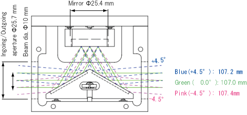
-4.5º〜 4.5º |
| Optical distance along the axis (mm) | 107 〜 108 |
| Applicable beam dia. | > Φ12 mm |
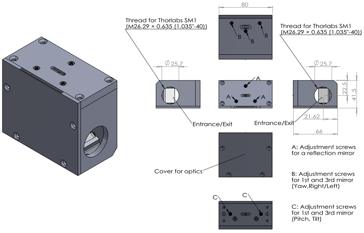
| Unit Size (mm) | 80 × 41.5 × 66 |
| Weight (g) | 380 |
Outline dimensions (mm)※
Optical path(Angle(º) and length (mm))※
How to fix the IRMU to the optional rotation stage
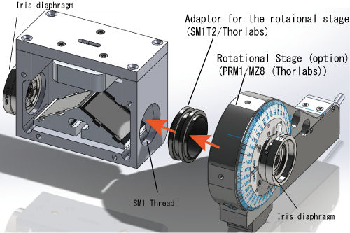
Others
Please ask us about your request or customization on the outline shape, size, beam size, field of view and so on.
- ※
- Under the condition of no iris diaphragms and no adaptors.
Other info
Pictures
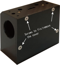
The cover for the optics of the IRMU.
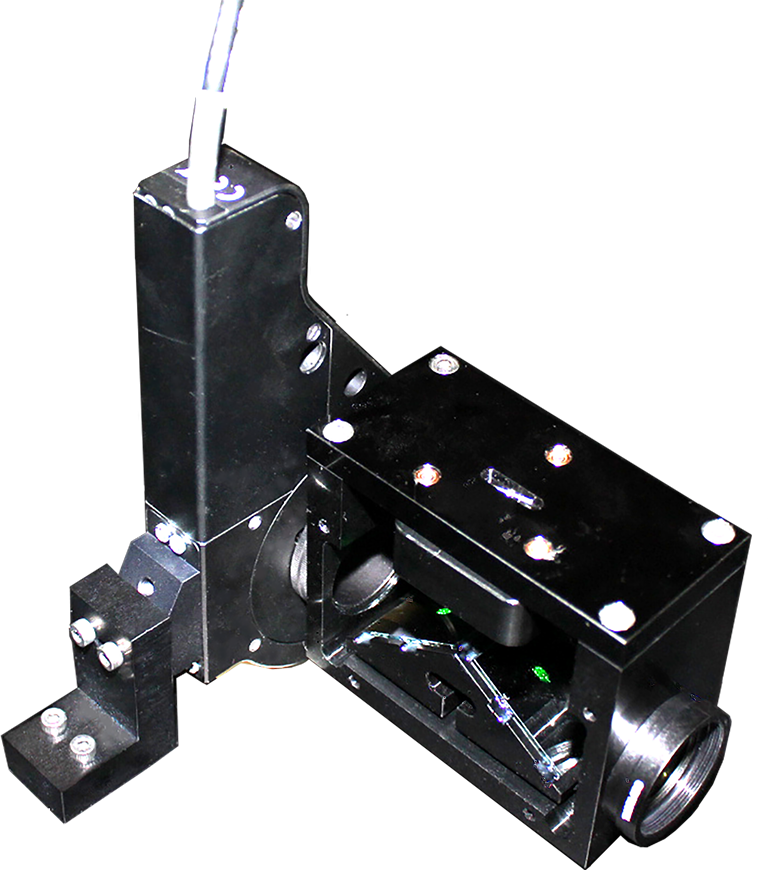
Example to fixing the IRMU to the rotational stage
Adjustment
you can rotate the image actively with the combination with the rotation device. To fixe the rotation center of the image, you need to adjust the mirrors and the rotation device according to the requirements below;
Requirement for the fixed ration center of the image.
- The axis of the ingoing beam consists with the axis of the outgoing beam.
- The optical axis consists with the axis of the rotational device.
To meet the requirements, the adjustment of the rotation device in x- and y- position and the tilt. You can see the reference below for the adjustment.
References:
Donald, L. Sullivan, Alignment of Rotational Prisms,Applied Optics, Vol. 11 pp2028-2032, 1972